3.2 Projections
Spatial observations need to be georeferenced, i.e., associated with specific geometric objects for which the location is represented in a two-dimensional Cartesian coordinate system (i.e., on a flat map). Since all observations originate on the surface of the three-dimensional near-spherical earth, this requires a transformation from three to two dimensions.
The transformation involves two concepts that are often confused by non-geographers, i.e., the geodetic datum and the projection. The topic is complex and forms the basis for the discipline of geodesy. A detailed treatment is beyond the current scope, but a good understanding of the fundamental concepts is important. The classic reference is Snyder (1993), and a recent overview of a range of technical issues is offered in Kessler and Battersby (2019).
The basic building blocks are degrees (and minutes and seconds) latitude and longitude that situate each location with respect to the equator and the Greenwich Meridian (near London, England). Longitude is the horizontal dimension (x), and is measured in degrees East (positive) and West (negative) of Greenwich, ranging from 0 to 180 degrees. Since the U.S. is west of Greenwich, the longitude for U.S. locations is negative. Latitude is the vertical dimension (y), and is measured in degrees North (positive) and South (negative) of the equator, ranging from 0 to 90 degrees. Since the U.S. is in the northern hemisphere, its latitude values will be positive. Latitude and longitude are typically given as decimal degrees, but, if not, a conversion from degrees, minutes and seconds is straightforward.
In order to turn a geographic description, such as an address, into latitude-longitude degrees, it is necessary to adhere to a so-called geodetic datum, a three-dimensional coordinate system or model that represents the shape of the earth. Currently, the most commonly used datum is the World Geodetic System of 1984, WGS 84, which represents the earth as an ellipsoid (and not as a perfect sphere). In North America, an alternative is NAD 83, the North American Datum of 1983. In practice, for U.S. locations, there is not much difference between the two. Both these standards are about to be replaced by reference frames that take advantage of Global Navigation Satellite Systems (GNSS).11
The second step in the process of georeferencing consists of converting the latitude-longitude coordinates to Cartesian x-y coordinates in a planar system, using a cartographic projection. Hundreds of projections have been developed, each addressing different aspects of the mathematical problem of converting a three-dimensional object (on a sphere or ellipsoid) to two dimensions (a flat map). In this conversion, every projection involves distortion of one or more fundamental properties of geographic objects: angles (sometimes confused with shape), area, distance and direction. It is important to be aware of this limitation, since many investigations rely on the computation of variables such as distance, or density (which involves area). The use of an inappropriate projection or distance metric may yield misleading results, especially for analyses that cover large areas (e.g., continent-wide).
For our purposes, three aspects are most important. One is to recognize whether spatial coordinates are projected (typically in units of feet or meters), or unprojected (i.e., in decimal degrees). To confuse matters more, the latter are sometimes referred to as a geographic projection, even though there is no projection involved. It is important to keep in mind that latitude and longitude are not expressed in distance units, but are degrees.
For example, a graph showing locations with longitude as the x-axis and latitude as the y-axis, treated as if they were regular distance units, can be misleading, even though it is seen quite commonly in publications. It ignores the fundamental property that latitude and longitude are degrees (angles). Similarly,
the calculation of Euclidean distance is only supported for projected coordinates and should not be performed on longitude-latitude pairs. In many instances, GeoDa will generate a warning when an attempt to compute distances with decimal degrees is made, but this cannot be detected in all situations.
A second aspect is to be aware of the characteristics of a particular projection that is being used. Specifically, it is important to know whether the projection respects properties such as area (equal area) or distance (equidistant), although such properties typically only pertain to a subset of the projected map.12
A final important aspect is to make sure that layers are in the same projection when combined. GeoDa has some functionality to reproject layers on the fly to accomplish this, but it is not fail-safe.
3.2.1 Coordinate reference system (CRS)
A coordinate reference system or CRS is a formal representation of location. It typically contains both a datum and a particular projection, as well as some information on the location of the coordinate center, units of measurement and related items. A CRS is identified by a code, such as an EPSG code, referred to as such because it was originally developed by the European Petroleum Survey Group (EPSG).
Interestingly, the lack of a projection, i.e., coordinates as simple latitude-longitude decimal degrees, has an EPSG code of 4326. As mentioned, this is sometimes referred to as a geographic projection, even though strictly speaking no projection is involved. Nevertheless, identifying latitude and longitude coordinates with a CRS of EPSG 4326 will provide a valid point of departure, Without it, there would be no information on what the coordinates represent. This is critical for use in later transformations (see Section 3.2.3).
GeoDa uses the proj4 convention to specify the CRS. This
is compatible with the open source PROJ library upon which the projection functionality is built.13 Specifically, in order to save a spatial layer that is expressed as latitude-longitude decimal degrees, the proper entry in the CRS box is:
+proj=longlat +ellps=WGS84 +datum=WGS84 +no_defs
3.2.2 Selecting a projection
Non-geographers are often at a loss when faced with specifying an appropriate projection. An excellent resource in this respect is the web site
spatialreference.org, which contains literally hundreds
of projection definitions that can be easily searched.14 For each projection, there is a summary of its properties and a list of its CRS specification in a range of different formats. For example, this includes the format used by ESRI in the *.prj files (part of the shape file specification), as well as the proj4 specification used by GeoDa.
While it is perfectly fine to use locations expressed as latitude-longitude decimal degrees, it is imperative to use the proper mathematical operations when computing properties like area and distance. For the latter, it is necessary to use great circle distance (arc distance), which is expressed in terms of the angles represented by latitude and longitude (see Chapter 11). In addition, the proper conversion of the great circle distance from angular units to distance unit (e.g., miles or kilometers) needs to differentiate by degree latitude. The implementation in GeoDa is only approximate and uses the distances at the equator.
In practice, it is preferred to use projected coordinates so that Euclidean distance operations and area calculations are straightforward to perform. For North America, a useful projection is universal transverse Mercator, or UTM. The country is divided into parallel zones, as shown in Figure 3.1. With each zone corresponds a specific projection that is represented by a CRS (e.g., an ESPG code).15
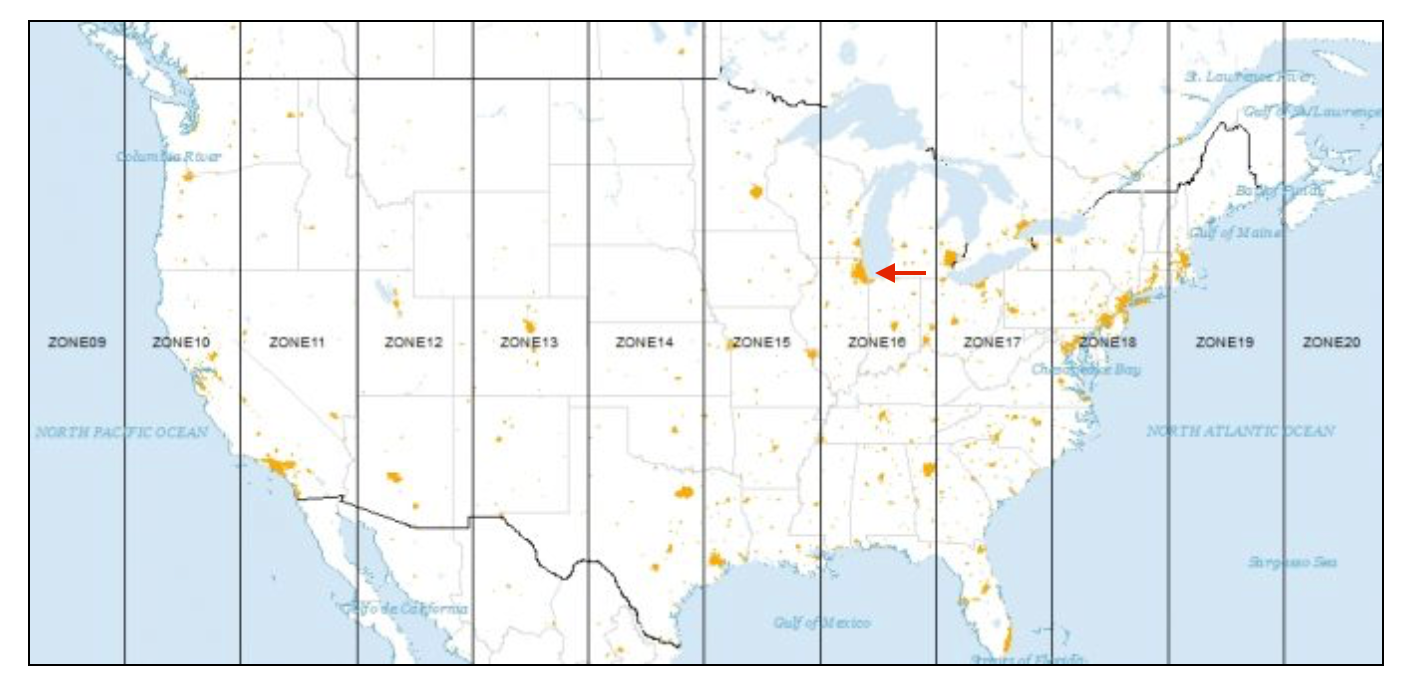
Figure 3.1: UTM zones for North America (source: GISGeography)
Let’s say we need a projection for locations in Chicago (indicated by the arrow on the figure). From the map, we can see that this city is located in UTM zone 16 (north – there is a southern hemisphere equivalent). Searching the spatialreference.org site for this projection yields a list of specifications (i.e., combinations of different datums). For example, for a WGS84 datum we can find an associated EPSG code of 32616. In the proj4 format, the corresponding CRS is:
+proj=utm +zone=16 +ellps=WGS84 +datum=WGS84 +units=m +no_defs
3.2.2.1 Specifying the CRS
As illustrated in the previous chapter, the File > Save As dialog contains a entry box at the bottom to specify the CRS for a spatial layer (see Figures 2.12 and 2.13). This will yield a new layer with the proper projection. An alternative approach that avoids the need to type in the actual proj4 specification is considered next.
3.2.3 Reprojection
To avoid the manual entry of the correct CRS code, the Save As
process in GeoDa provides an alternative that does not need an explicit specification, but
requires the presence of another layer with the desired projection. The CRS information
is then copied from that other layer and used in the reprojection of a current layer.
For example, consider the 77 Chicago community areas expressed in latitude-longitude coordinates in Figure 2.4. We saw how the locations of the carjackings in Figure 2.7 suggested a somewhat different shape for the city, because it was expressed in he State Plane Illinois East NAD 1983 projection (EPSG 3435). To convert the polygon community areas to the same projection, we could enter the proper proj4 specification in the CRS box.
An alternative is to copy the CRS information from a different layer. For example, after opening the community area file (Chicago_community_areas.shp) and invoking File > Save As, the CRS box shows the proj4 specification for latitude-longitude degrees, as in Figure 3.2. Instead of typing in the new specification, the small globe icon to the right can be selected to load a CRS specification from another file.

Figure 3.2: Load CRS from another layer
This brings up a file load interface into which the file name for the point shape file with the carjacking locations can be specified (Chicago_carjack_2020_pts.shp). The easiest way to accomplish this is by dragging the file name into the Drop file here area. Once the file name is loaded, the contents of the CRS box change to the new proj4 specification, as in Figure 3.3.

Figure 3.3: New CRS from another layer
After saving the new file (e.g., as community_areas_proj.shp), the current project should be closed. A new project is started by loading the just created projected layer. The corresponding themeless base map is as in Figure 3.4. The more compressed shape matches the layout of the car jacking locations in Figure 2.7.
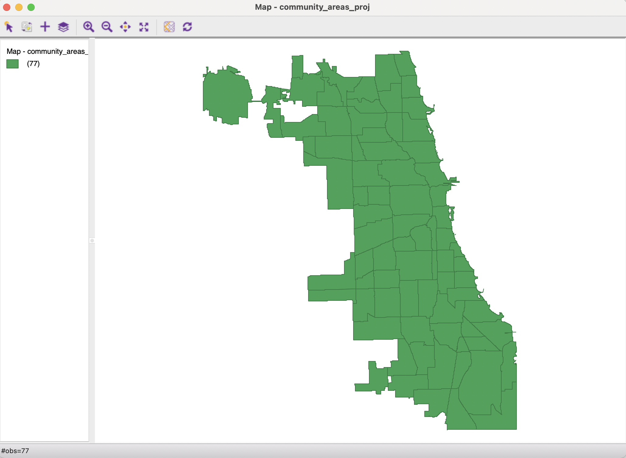
Figure 3.4: Reprojected Chicago community areas layer
For details, see https://geodesy.noaa.gov/datums/newdatums/index.shtml.↩︎
For a detailed technical discussion, see, for example Kessler and Battersby (2019).↩︎
For more details on the fundamentals behind the UTM projection, see, for example, the GISGeography site at https://gisgeography.com/utm-universal-transverse-mercator-projection/.↩︎