3.8 Linked Multi-Layers
In the previous example, the connection between two layers is used to compute a new variable (e.g., the number of points in a polygon). An additional feature of the multi-layer architecture is that a connection can be established between observations in two layers. A typical application of this feature is to show the connection between two point layers, e.g., where one contains the location of headquarters and the second of branches, connected by a shared corporate ID. The latter is critical, since the observations in the two layers must share a common key.
The linkage is established through the Highlight Association options in the Map Layer Settings dialog (Figure 3.20). There are three aspects of this: Set Highlight Association, Clear Highlight Association and Change Associate Line Color.
Once the linkage is established, it can be highlighted for any selection in the current map layer. Each observation in the current map is connected to the matching observation in the other layer, either a point location or the centroid of a polygon. It is important to remember that any selection pertains to the current map layer, irrespective of which layer is shown on top in the map view.
3.8.1 Specifying an inter-layer linkage
The layer arrangement from Figure 3.19 has the (projected) car jacking locations loaded first (current map), followed by the (projected) community area boundaries. Observations in both layers share the community area identifier, Commu_Area in the point layer, and area_num_1 in the polygon layer.
Selecting Set Highlight Association from the options generates the dialog shown in Figure 3.29. This interface brings all the elements together to connect observations in the two layers through a series of drop down lists.
The point of departure is the current layer, shown at the top of the dialog (Chicago_carjack_2020_pts). The first drop down list, Select layer is to select the layer to link with. In the example, there is only one option, community_areas_proj. Next is the key for that layer (field), area_num_1, and the corresponding key in the current layer (associated), Commu_Area. Finally there is a check box to activate connection lines between the two layers.
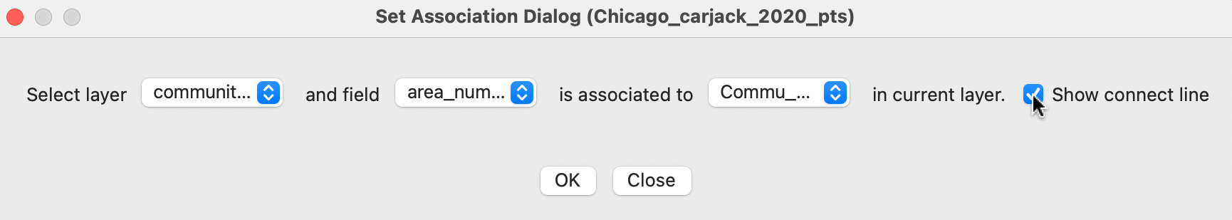
Figure 3.29: Set association dialog
3.8.2 Visualizing linked selections
The choices in the dialog of Figure 3.29 establish the connection between the two layers, but this is only activated through an actual selection in the current map (see Section 2.5.4). For example, in Figure 3.30, point locations have been selected that belong to three different community areas. A line connects each selected point with the centroid of the linked area. The default color is red, but this can be readily changed through the Change Associate Line Color option.
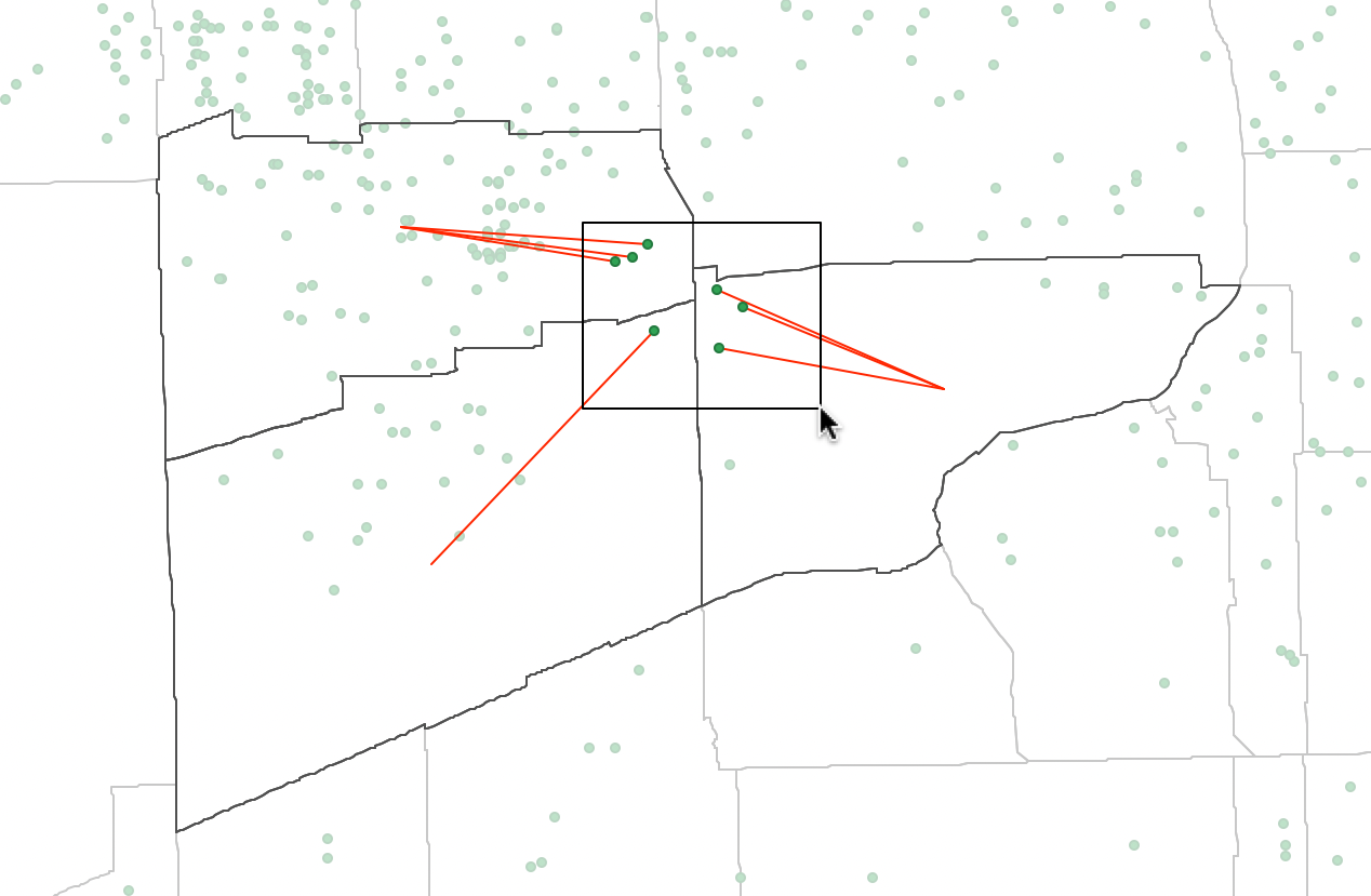
Figure 3.30: Linked selection
The operation can also be reversed, i.e., by making the polygon layer the current map from which observations can be selected, showing the linked points.